
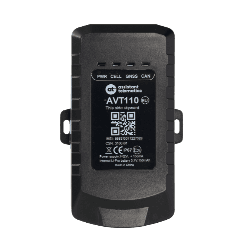
GPS Trackers
AVT110
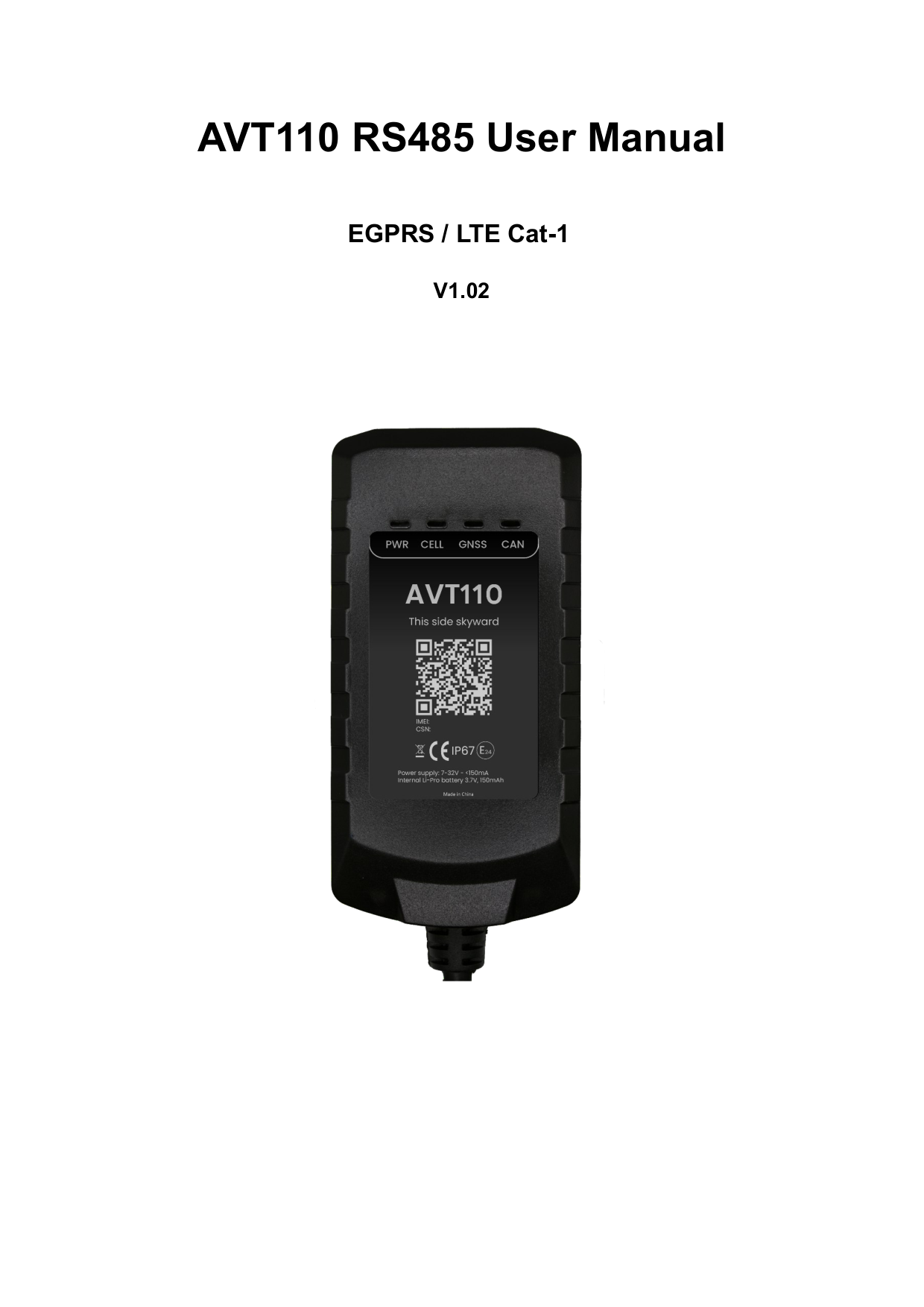
RS485 User manual
AVT110 RS485 User Manual
Version 1.02 — Nov 7, 2025
This manual covers installation, power connection, CAN setup, and operation of the AVT110/AVT111 GNSS tracker family (RS485 interface). Use the structured sections below for quick reference, or open the full PDF for diagrams and the complete document.
Introduction
The AVT110 and AVT111 are compact GNSS trackers designed for a wide variety of vehicle tracking applications. They have multiple I/O interfaces that can be used for monitoring or controlling external devices.
The built-in GNSS receiver has superior sensitivity and fast time to first fix. Seven-band LTE-FDD in Europe and GSM/GPRS 850/900/1800/1900 MHz allow the tracker's location to be monitored in real time or periodically tracked by a backend server and mobile devices.
The built-in 3-axis accelerometer supports driving behaviour monitoring, motion detection, and extended battery life through sophisticated power management algorithms. A built-in CAN module is included.
Specifications
| Parameter | Value |
|---|---|
| Dimensions | 112 mm × 57 mm × 27.5 mm |
| Network | EGPRS: GSM850/GSM900/DCS1800/PCS1900; LTE Cat-1: B1, B3, B5, B7, B8, B20, B28 |
| GNSS (optional) | GPS, GLONASS, BDS, GALILEO |
| Bluetooth | BLE 5.3 |
| Sensors & interface | G-Sensor; 1-Wire; RS485; IGN input; digital output; analog/negative trigger input; CAN1 L/H; CAN2 L/H; K-Line |
| Battery | 3.7 V 150 mAh rechargeable Li-polymer |
| IP rating | IP67 |
| Power supply | 7 – 32 V |
| Operating temperature | −20 °C to +60 °C |
| LED indicators | Power, NET (CELL), GNSS, CAN |
| Debug port | USB Type-C |
Interface definition (14 PIN)
The tracker has a 14 PIN interface connector for power, inputs, outputs, 1-Wire, RS485, CAN, and K-Line:
| PIN | Defined | Color | Comment |
|---|---|---|---|
| 1 | VIN | Red | External DC power input, 8–32 V |
| 2 | GND | Black | Power and digital ground |
| 3 | IGN | White | Ignition input, positive trigger |
| 4 | ADIN | Orange | Analog input and negative trigger input multiplexing |
| 5 | OUT1 | Brown | Digital output, open drain, 150 mA max, with latch circuit |
| 6 | 1W Data | Yellow | Data for 1-Wire |
| 7 | 1W VDD | Blue | VDD for 1-Wire |
| 8 | RS485 A | Gray | RS485 A |
| 9 | RS485 B | Light Blue | RS485 B |
| 10 | CAN2 H | Purple | CAN 2 positive |
| 11 | CAN2 L | Purple/White | CAN 2 negative |
| 12 | CAN1 H | Green | CAN 1 positive |
| 13 | CAN1 L | Green/White | CAN 1 negative |
| 14 | K-Line | Pink | Data for K-Line |
Install a SIM card
- Open the case and ensure the unit is not powered.
- Slide the holder right to open the SIM card holder.
- Insert the SIM card with the gold contact area facing down. Align the cut mark.
- Close the SIM card holder and the case.
Internal backup battery
The device has an internal backup 150 mAh Li-ion battery. Refer to the battery switch position shown in the full PDF manual before first use.
Power connection
VIN (PIN1) / GND (PIN2) are the power input pins. The input voltage range is 7 V to 32 V. The device is designed for common 12 V or 24 V vehicle systems without external transformers.
Ignition detection
| Logical status | Electrical characteristics |
|---|---|
| Active | 7 V to 32 V |
| Inactive | Open |
IGN (PIN3) is used for ignition detection. Connect this pin to the ignition key RUN position when possible. An alternative is a non-permanent power source available only when the vehicle is running (for example, FM radio power).
IGN can be configured to start transmitting to the backend when ignition is on and enter power-saving mode when ignition is off.
Terminal status LED
| LED | Device status | LED status |
|---|---|---|
| CAN | Operating mode, CAN-BUS or J1708 active (only one) | Green flashes once every 1 s |
| CAN | Operating mode, CAN-BUS(es) and J1708 sleep or disabled | Green flashes once every 4 s |
| CAN | Low power mode (sleep) | OFF |
| CAN | CAN-BUS codes synchronization | Red flashes quickly (~7×/s) |
| CAN | CAN-BUS synchronization finished successfully | Green ON (after sync) |
| CAN | CAN-BUS sync failed (wires connected, codes not recognized) | Red ON (after sync) |
| CAN | CAN-BUS sync failed (no CAN connection or CAN sleep) | Red flashes 0.5 s / green 0.5 s |
| GNSS | GNSS chip powered off | OFF |
| GNSS | No data or format error | High-speed flashing |
| GNSS | Searching GNSS | Medium-speed flashing |
| GNSS | GNSS fix acquired | ON |
| CELL | Searching network | Fast flashing |
| CELL | Registered on network | Slow flashing |
| PWR | No external power, battery < 3.5 V | OFF |
| PWR | No external power, battery < 3.7 V | Slow flashing |
| PWR | External power connected, battery charging | Fast flashing |
| PWR | External power connected, battery fully charged | ON |
G-sensor direction
The internal 3-axis sensor supports driving behaviour monitoring, crash detection, and motion detection. Mount the device according to the motion sensor orientation shown in the full PDF manual.
CAN interface
There are two CAN interfaces: CAN2L/CAN2H and CAN1L/CAN1H. CAN2 can also be connected to the vehicle J1708 interface.
Connection diagram for light cars
CAN1 and CAN2 can connect to a light car's CAN-BUS and OBD interface as described in the vehicle-specific installation manual.
Trucks using J1939 and J1708
Connect J1939 to CAN1 and J1708 to CAN2. For CAN connection points on a specific truck model, refer to that model's installation manual.
FMS connector for trucks
The FMS connector connects to CAN1. FMS connector shape and pinout vary between truck makes and models — see the full PDF for an illustrative diagram.
Connect the tachograph to CAN2, K-Line, and GND while the vehicle CAN-BUS connects to CAN1. If only the tachograph is connected, use CAN2, K-Line, GND, and run auto-synchronization.
CAN-BUS synchronization
CAN-BUS code synchronization lets the tracker detect the connected vehicle model. Switch ignition on and send AT@RTO=AVT110,14,2,,,,,FFFF# after installation to start synchronization. Observe the CAN LED during the process. See AT@RTO sub-commands 13 and 14 in the protocol documentation for details.
CAN LED indicator
| LED pattern | Work mode |
|---|---|
| Blinks green once every 1 s | Operating: CAN-bus, J1708, or D8 active (one bus) |
| Blinks green twice every 1 s | Operating: two buses active |
| Blinks green thrice every 1 s | Operating: three buses active |
| Blinks green once every 4 s | CAN-bus(es) and J1708 sleep or disabled |
| Off | Low power mode (sleep) |
| Blinks red quickly (~7×/s) | CAN-bus codes synchronization |
| Green on (after sync) | Synchronization finished successfully |
| Red on (after sync) | Sync failed — wires connected but codes not recognized |
| Flashes red 0.5 s on / green 0.5 s on | Sync failed — no CAN connection or CAN sleep |
| Blinks red twice every 1 s | Fail-safe mode |
| Blinks red once every 2 s | Invalid configuration (e.g. vehicle not synchronized) |
| Flashes green 2 s on / 100 ms off | Supervised mode (configurator connected) |
| Flashes green 1 s on / 100 ms off | Development test mode |
| Red on (after power-on) | Device startup failed — return to producer |
Firmware upgrade
Firmware and configuration files are supplied by the manufacturer. CAN firmware or configuration upgrade is performed via AT@CFU. Refer to the AT@CFU command in the protocol documentation.
AVT110 — RS485 User manual
v1.02 · 2025-11-07 · Release
Page 1 of 15
If the preview does not load, use Download or Open in new tab.