
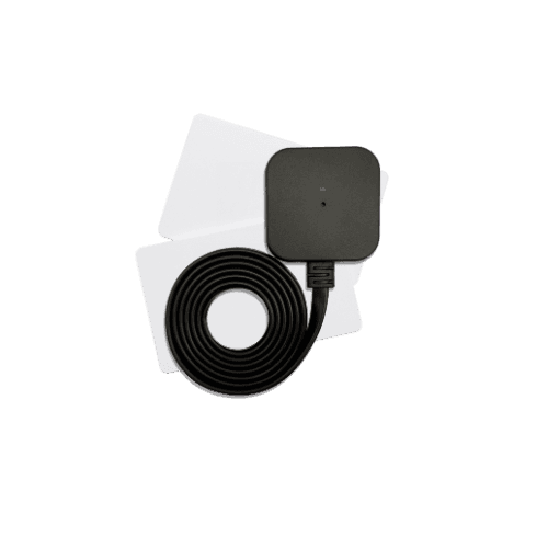
Accessories
AWR201
User manual
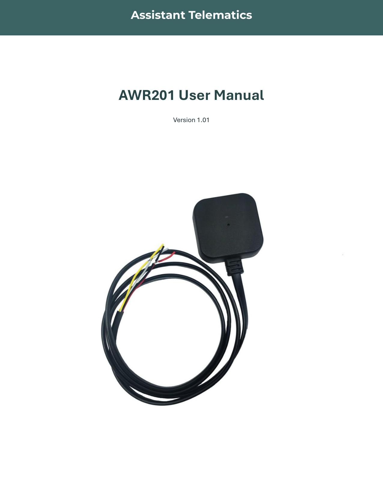
AWR201 User Manual — 1-Wire RFID Reader
Revision 1.01 — AWR201
This manual covers the AWR201 1-Wire RFID reader — general description, specifications, wiring, and firmware upgrade. Use the structured sections below for quick reference, or open the full PDF for the complete document.
General description
AWR201 supports 4-byte and 7-byte ID formats at the same time. The reader supports three card types: ISO14443A, ISO14443B, and ELID.
64-bit lasered ROM (4-byte ID):
The 4-byte ID type uses a unique 64-bit ROM code. The first 8 bits are a 1-Wire family code, the next 48 bits are a unique serial number, and the last 8 bits are a CRC of the first 56 bits.
- ISO14443A serial numbers are 4 bytes (00000000 to FFFFFFFF), zero-padded on the left. Example: card number 123456789 → serial 075BCD150000.
- ELID card data includes a 1-byte facility code and a 4-byte card number (00000000 to FFFFFFFF), zero-padded. Example: facility code 0x0B, card number 0007864739 → serial 0B007801A300.
72-bit lasered ROM (7-byte ID):
The 7-byte ID type uses a unique 72-bit ROM code. The first 8 bits are a 1-Wire family code, the next 56 bits are a unique serial number, and the last 8 bits are a CRC of the first 64 bits. The 7-byte ID type uses family code 0x66.
ISO14443A serial numbers for 7-byte ID are 7 bytes (00000000000000 to FFFFFFFFFFFFFF).
Technical specifications
| Parameter | Specification |
|---|---|
| Weight | 68 g |
| Dimensions | 41 × 41 × 11 mm |
| Operating voltage | 7 – 32 V |
| Operating temperature | −20 °C ~ +80 °C |
| Storage temperature | −20 °C ~ +85 °C |
| Frequency | 13.56 MHz / 125 kHz |
LED and wiring
| Item | Description |
|---|---|
| Red LED | Power ON |
| Blue LED | Flashes 3 times when sending data |
| Red wire (VDD) | 7 – 32 V |
| Black wire | Ground |
| White wire | 1-Wire data |
| Yellow wire | Buzzer |
Firmware upgrade
Preparation:
Upgrade procedure:
- Connect the upgrade toolkit to the PC.
- Connect the wires one by one in the following order: red → red, black → black, white → white (the white wire must be connected last).
- Run the upgrade tool on your PC and press Choose file.
- Open the COM port and press Start.
- When the file is successfully loaded, press Update (the tool displays which file is currently on the upgrade board).
- With all wires connected and the file uploaded, place the RFID card on top of the reader and press the button on the upgrade board.
- Update is successful when the upgrade board beeps two times and the green LED flashes. The update has failed if the board beeps five times and the red LED lights up.
- When the upgrade is complete, disconnect the white wire first, then black and red.
AWR201 — User manual
v1.01 · 2025 · Release
Page 1 of 5
If the preview does not load, use Download or Open in new tab.