
GPS Trackers
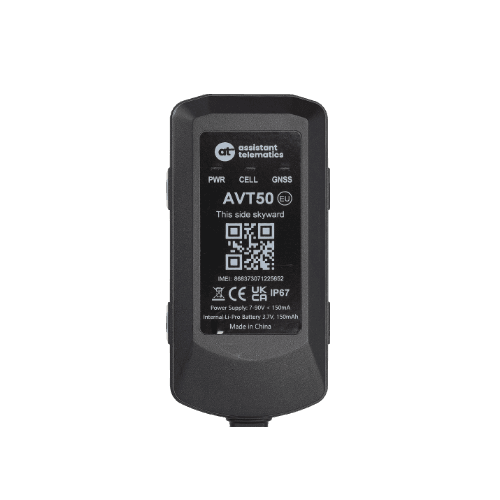
AVT50
Protocol
AVT50 Tracker Protocol
Revision 2.05 — May 7, 2026 — +DFI message, IGN BLE relay limits, PEO polygon fence
AVT50 Tracker Protocol R2.05 defines the data stream format, configuration commands, and message structures used between the AVT50 GNSS tracker and backend server. Use the sections below for a structured overview, or open the full PDF for complete command parameters and field definitions.
AVT50 — Protocol
v2.05 · 2026-05-07 · Release
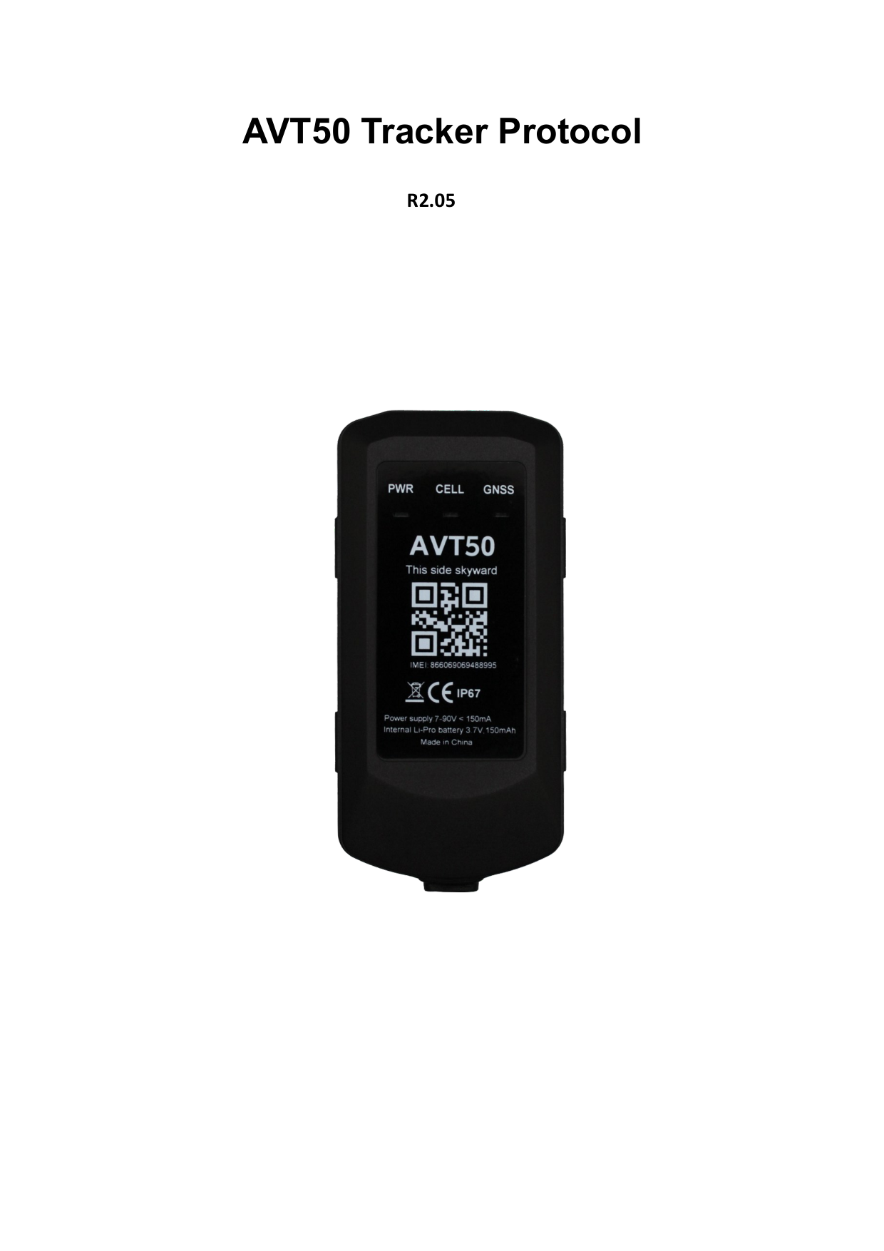
Page 1 of 105
If the preview does not load, use Download or Open in new tab.
Revision history
| Revision | Date | Description |
|---|---|---|
| 1.01 | 2024-11-03 | Initial release |
| 1.02 | 2025-03-10 | GNSS Satellites Number in AT@GCS; Charging Mode; Event Data Mask cleanup |
| 1.03 | 2025-05-10 | AT@BSS BLE scan; AT@JAM/TAS; AT@ETS/EHS; external temp/humidity events; +TCF |
| 1.04 | 2025-09-10 | GNSS Timeout parameter in AT@GCS |
| 1.05 | 2025-09-24 | AT@SSI second server; TLS (TCR/TCL); MQTT (MQT); AT@UPC; AT@BWS; upgrade config event |
| 2.01 | 2026-01-12 | AT@GGF geo-fence GNSS filter; GNSS spoofing alarm (type 39); JAM LTE signal params |
| 2.02 | 2026-02-03 | ECL Trigger Mask in +RPT; ECL Trigger Report in AT@ECL |
| 2.03 | 2026-02-25 | AT@PEO polygon fence; AT@BCS/BRY/BOS BLE connection and relay; PEO events 40/41 |
| 2.04 | 2026-03-23 | TOW/MOV/IGN/HBS/CRA parameter updates; JAM GSM params; ABK100 whitelist in AT@BSS |
| 2.05 | 2026-05-07 | +DFI message; IGN output limits and BLE relay bits; ABR100 in AT@BCS; IGN debounce |
Data stream format
Communication includes upstream (device → server) and downstream (server → device) data streams over the cellular network. Upstream carries responses to downlink commands, heartbeat packets, and unsolicited reports. Downstream carries configuration, query commands, and responses to uplink messages.
Frame types
| Direction | Encoding | Frame | Usage |
|---|---|---|---|
| Downstream | Printable ASCII | Configuration Command | Configure terminal parameters (AT@…=) |
| Downstream | Printable ASCII | Query Command | Query current parameters (AT@…?) |
| Downstream | Printable ASCII | +SACK | Server acknowledgement for +RPT messages |
| Downstream | Printable ASCII | +SHBD | Server response to +HBD heartbeat |
| Upstream | Printable ASCII | +QRY | Terminal response to a query command |
| Upstream | Printable ASCII | +HBD | Periodic heartbeat to maintain TCP/UDP connectivity |
| Upstream | Printable ASCII | +ACK / +NACK | Acknowledgement or rejection of configuration commands |
| Upstream | Hexadecimal | +RPT / -RPT | Real-time and buffered report messages |
Configuration commands
Configuration commands use the format AT@<KEY>=<password>,<parameters>,…,<serial># . Each command is protected by a password (default at) and ends with a 4-digit hexadecimal serial number and "#".
Example — main server settings:
AT@SIS=at,0,1,255.255.255.255,12345,,,0,0001#
Network commands
| Code | Command | Description |
|---|---|---|
| SIS | AT@SIS= | Main server IP, port, report mode (0 Stop / 1 TCP / 2 UDP / 3 MQTT), buffer, SACK enable, heartbeat, PDP/TLS, Resend Time No SACK |
| SSI | AT@SSI= | Second server settings (same parameters as SIS) |
| NIS | AT@NIS= | APN, credentials, network scan mode, Search No Signal Cover |
| MQT | AT@MQT= | MQTT client ID, topics, QoS, keep-alive (main or second server) |
| TCR | AT@TCR= | TLS certificate remote download (HTTP) |
| TCL | AT@TCL= | TLS certificate local download |
General commands
| Code | Command | Description |
|---|---|---|
| GMT | AT@GMT= | Greenwich Mean Time / time zone setting |
| GCS | AT@GCS= | Global configuration: Data Mask, Event Data Mask (incl. PEO status bits 21/24), LED, GNSS/AGPS, odometer, hour meter, charging mode, GNSS timeout |
| RRS | AT@RRS= | Regular GNSS report: mode, IGN/IGF intervals, corner angle, long standby wake-up |
| RTO | AT@RTO= | Real-time operation: reboot, power off, factory reset, realtime positioning, +DFI, satellite info |
| PCL | AT@PCL= | Preset command list (up to 32 commands) |
| ECL | AT@ECL= | Event-driven command list with ECL Trigger Report |
| GGF | AT@GGF= | Geo-fence GNSS filter and spoofing detection settings |
Alarm commands
| Code | Command | Description |
|---|---|---|
| MOV | AT@MOV= | Movement alarm with Motion Event Report |
| TOW | AT@TOW= | Towing (TOW) alarm detection |
| SPD | AT@SPD= | Speed alarm threshold and duration |
| GEO | AT@GEO= | Circular geo-fence settings (up to 32 zones) |
| PEO | AT@PEO= | Polygon fence settings (up to 50 zones) |
| HBS | AT@HBS= | Harsh behavior (driving style) with trigger interval |
| CRA | AT@CRA= | Crash detection with crash debounce |
| JAM | AT@JAM= | Jamming alarm (LTE and GSM signal thresholds) |
| TAS | AT@TAS= | Tilt alarm detection |
I/O, BLE, OTA, and debug
| Category | Code | Description |
|---|---|---|
| IO & ADC | IGN | Ignition and virtual ignition; Ignition On limit outputs mask, GNSS speed limit, debounce |
| IO & ADC | DAM | Digital and analog input multiplexing (incl. delta AIS) |
| IO & ADC | OUT | Digital output settings |
| IO & ADC | AOS | Alarm output mapping and trigger masks |
| BLE | BSS | BLE scan settings, iBeacon UUID filter, accessory whitelist check |
| BLE | BWS | BLE beacon whitelist (MAC groups, up to 256 entries) |
| BLE | BCS | BLE connection settings (ABK100, ABR100 relay encryption) |
| BLE | BRY | BLE relay output control |
| BLE | BOS | BLE alarm output wave shape |
| BLE | ETS | External temperature sensors (BLE) |
| BLE | EHS | External humidity sensors (BLE) |
| OTA | UPF | Firmware upgrade over the air (main MCU, network module, boot firmware) |
| OTA | UPC | Configuration upgrade over the air |
| OTA | BMS | Device management system: BMS server, report mode (Stop/TCP/UDP/MQTT), +BMR Data Mask |
| DEBUG | DBG | OTA debug log server and log mask |
Query commands
Query commands retrieve the current working parameters of the terminal. They use printable ASCII with comma-separated fields:
AT@<KEY>?<password>,,<serial>#
- AT@SIS?at,,# — query main server settings
- AT@SSI?at,,# — query second server settings
- AT@NIS?at,,# — query network (APN) settings
- AT@GMT?at,,# — query time settings
- AT@GCS?at,,# — query global configuration
- AT@RRS?at,,# — query regular report settings
- AT@GEO?at,,# — query geo-fence settings
- AT@PEO?at,,# — query polygon fence settings
Message format
Report, buffer, and heartbeat messages share a common frame structure with header, data, and tail zones:
| Zone | Fields | Encoding |
|---|---|---|
| Header | Head (5 B) + Length (2 B) + IMEI (8 B) + Device ID (1 B) | ASCII / HEX / HEX / HEX |
| Data | Variable payload + G-time (7 B) | HEX or ASCII |
| Tail | Serial number (2 B) + Tail "#" (1 B) | HEX / ASCII |
- +RPT / -RPT, +BMR / -BMR, +HBD — data zone encoded in hexadecimal (big-endian for multi-byte values)
- +SACK / +SHBD — fully ASCII encoded
- +ACK, +QRY, +ALL, +QNI, +VER, +GSV, +LSV, +BSV, +GAV, +SCF, +TCF, +DFI — data zone in ASCII with comma separators
Report messages (+RPT / -RPT)
+RPT frames are real-time reports generated and sent within 3 minutes. -RPT frames are historical reports stored in the device buffer and sent when connectivity is restored.
All GNSS-related messages and events share the same +RPT/-RPT hex-encoded format. The Data Mask and Event Data Mask in AT@GCS control which information zones are included.
Key +RPT Data Mask bits (AT@GCS)
| Bit | Field | Content |
|---|---|---|
| 0 | Multi-packet | Auto-enabled when message exceeds 256 bytes |
| 1 | Network type | Cellular network type |
| 2 | Battery | Voltage (mV) and level (%) |
| 3 | GNSS information | Fix type, HDOP, speed, azimuth, altitude, lat/lon, UTC time, satellite counts |
| 4 | Cell information | MCC, MNC, LAC, Cell ID, CSQ |
| 7 | Upgrade information | Firmware upgrade status |
| 8 | Event data | Main power, ignition, motion, mileage, GEO/PEO status, hour meter, crash, tilt, TLS, digital I/O |
| 19 | BLE information | BLE scan results and sensor data |
| 20 | BLE iBeacon | iBeacon scan results |
| 22 | Upgrade config | Configuration OTA status |
Event types
| Type | Event |
|---|---|
| 0 | Terminal power |
| 1 | Regular report |
| 2 | Moving |
| 3 | Battery alarm |
| 7 | Crash alarm |
| 11 | Upgrade firmware |
| 12 | External temperature alarm |
| 13 | Ignition |
| 14 | Main power alarm |
| 15 | Tow alarm |
| 16 | Over speed alarm |
| 19 | Harsh behavior alarm |
| 20 | G-sensor self-calibration |
| 21 | Geo-fence alarm |
| 22 | Digital input 1 |
| 27 | Output alarm |
| 28 | Delta AIS alarm |
| 29 | PDP alarm |
| 30 | BLE common info |
| 31 | External humidity alarm |
| 32 | Jamming alarm |
| 33 | Tilt alarm |
| 34 | BLE iBeacon info |
| 35 | TLS certificate download |
| 38 | Upgrade configuration |
| 39 | GNSS spoofing alarm |
| 40 | PEO fence alarm |
| 41 | PEO fence over-speed alarm |
| 43 | ECL trigger alarm |
Buffer messages (+BMR / -BMR)
+BMR frames are real-time BMS reports. -BMR frames are buffered BMS reports sent when connectivity is restored. Configure via AT@BMS.
| Parameter | Description |
|---|---|
| Report Mode | 0 = Stop, 1 = TCP, 2 = UDP, 3 = MQTT |
| Buffer Mode | 0 = disabled, 1 = low priority, 2 = high priority |
| BMS Server IP / Port | Device management server address |
| Connection Life | 0 or 5–300 seconds TCP keep-alive |
| Report Interval | 1–2880 minutes |
| BMR Data Mask | Battery level, config version, IGN state, GNSS info, SIM info, module version, boot firmware |
Heartbeat and acknowledgement
| Frame | Direction | Description |
|---|---|---|
| +HBD | Device → server | Periodic heartbeat when report mode is TCP or UDP (interval set in AT@SIS) |
| +SHBD | Server → device | Server response to +HBD |
| +ACK | Device → server | Confirms a valid configuration command was received |
| +NACK | Device → server | Rejects an illegal configuration command |
| +SACK | Server → device | Server acknowledgement when SACK Enable is set |
Command query responses
| Frame | Description |
|---|---|
| +QRY | Response to a single query command |
| +ALL | Bulk response with all configured parameters |
| +QNI | Network information (APN, IMSI, ICCID, CSQ, cell ID) |
| +VER | Firmware and hardware version information |
| +GSV | GPS satellite visibility |
| +LSV | GLONASS satellite values |
| +BSV | BEIDOU satellite values |
| +GAV | GALILEO satellite values |
| +SCF | Server configuration fields |
| +TCF | Terminal configuration fields (including tilt calibration) |
| +DFI | Device file information (requested via AT@RTO sub-command 16) |
Terms and abbreviations
| Term | Meaning |
|---|---|
| ACK | Acknowledgement |
| AGPS | Assisted Global Positioning System |
| APN | Access Point Name |
| BLE | Bluetooth Low Energy |
| GNSS | Global Navigation Satellite System |
| IMEI | International Mobile Equipment Identity |
| IoT | Internet of Things |
| MQTT | Message Queuing Telemetry Transport |
| PEO | Polygon fence (geo zone) |
| RPT | Report message |
| SACK | Server acknowledgement |
| TCP / UDP | Transmission Control / User Datagram Protocol |
| TLS | Transport Layer Security |
| TOW | Towing detection |
| UTC | Coordinated Universal Time |
| VG | Virtual Ignition |
| VGN / VGF | Virtual Ignition On / Off |