
GPS Trackers
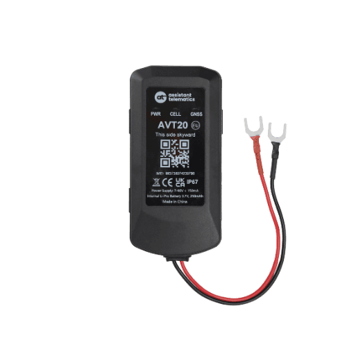
AVT20
User manual
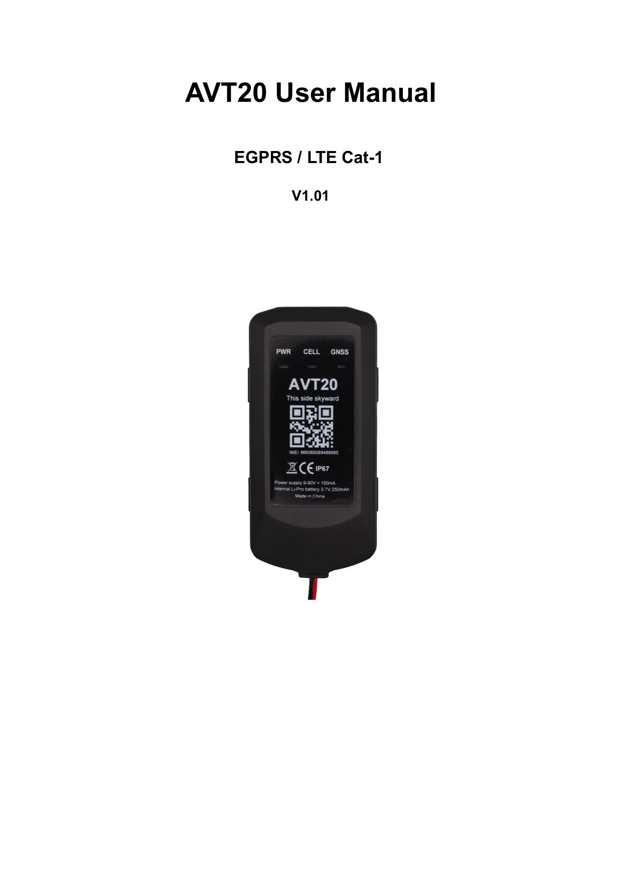
AVT20 User Manual
Revision 1.01 — Dec 10, 2024 — Initial release
This manual covers installation, power connection, and operation of the AVT20 GNSS tracker. Use the structured sections below for quick reference, or open the full PDF for the complete document.
Introduction
The AVT20 is a compact GNSS tracker designed for a wide variety of vehicle tracking applications. It has multiple I/O interfaces that can be used for monitoring or controlling external devices.
Its built-in GNSS receiver has superior sensitivity and fast time to first fix. Seven-band LTE-FDD in Europe and GSM/GPRS 850/900/1800/1900 MHz allow the AVT20's location to be monitored in real time or periodically tracked by a backend server and mobile devices.
The built-in 6-axis accelerometer and gyroscope support driving behaviour monitoring and motion detection.
Specifications
| Parameter | Value |
|---|---|
| Dimensions | 97 mm × 48 mm × 18 mm |
| Network | EGPRS: GSM850/GSM900/DCS1800/PCS1900; LTE Cat-1: B1, B3, B5, B7, B8, B20, B28 |
| GNSS (optional) | GPS, GLONASS, BDS, GALILEO |
| Bluetooth | BLE 5.3 |
| Sensors & interface | G-Sensor (6-axis accelerometer and gyroscope) |
| Battery | 3.7 V 250 mAh rechargeable Li-polymer |
| IP rating | IP67 |
| Power supply | 7 – 90 V |
| Operating temperature | −20 °C to +60 °C |
| LED indicators | Power, NET (CELL), GNSS |
| Debug port | USB Type-C |
Interface definition (2 PIN)
AVT20 has a 2 PIN interface connector for power and ground:
| PIN | Defined | Color | Comment |
|---|---|---|---|
| 1 | VIN | Red | External DC power input, 7 – 90 V |
| 2 | GND | Black | Power and digital ground |
Install a SIM card
- Open the case and ensure the unit is not powered.
- Slide the holder right to open the SIM card holder.
- Insert the SIM card with the gold contact area facing down. Align the cut mark.
- Close the SIM card holder and the case.
Internal backup battery
AVT20 has an internal backup 250 mAh Li-ion battery for continued operation when external power is unavailable.
Power connection
PWR (PIN1) / GND (PIN2) are the power input pins. The input voltage range is 7 V to 90 V. The device is designed for common 12 V and 24 V vehicle systems without external transformers.
Terminal status LED
| LED | Device status | LED status |
|---|---|---|
| GNSS | GNSS chip is powered off | OFF |
| GNSS | No data or data format error | High speed flashing |
| GNSS | Searching GNSS information | Medium speed flashing |
| GNSS | GNSS information acquired | ON |
| CELL | Searching network | Fast flashing |
| CELL | Registered on network | Slow flashing |
| PWR | No external power, battery < 3.5 V | OFF |
| PWR | No external power, battery < 3.7 V | Slow flashing |
| PWR | External power connected, battery charging | Fast flashing |
| PWR | External power connected, battery fully charged | ON |
G-sensor direction
AVT20 has an internal 6-axis accelerometer and gyroscope supporting driving behaviour monitoring, crash detection, and motion detection. Mount the device according to the motion sensor orientation shown in the full manual.
Product parts list
- AVT20 locator
- 3M backing sticker
- Case screws (4 pcs)
AVT20 — User manual
v1.01 · 2024-12-10 · Release
Page 1 of 9
If the preview does not load, use Download or Open in new tab.