
Tacho
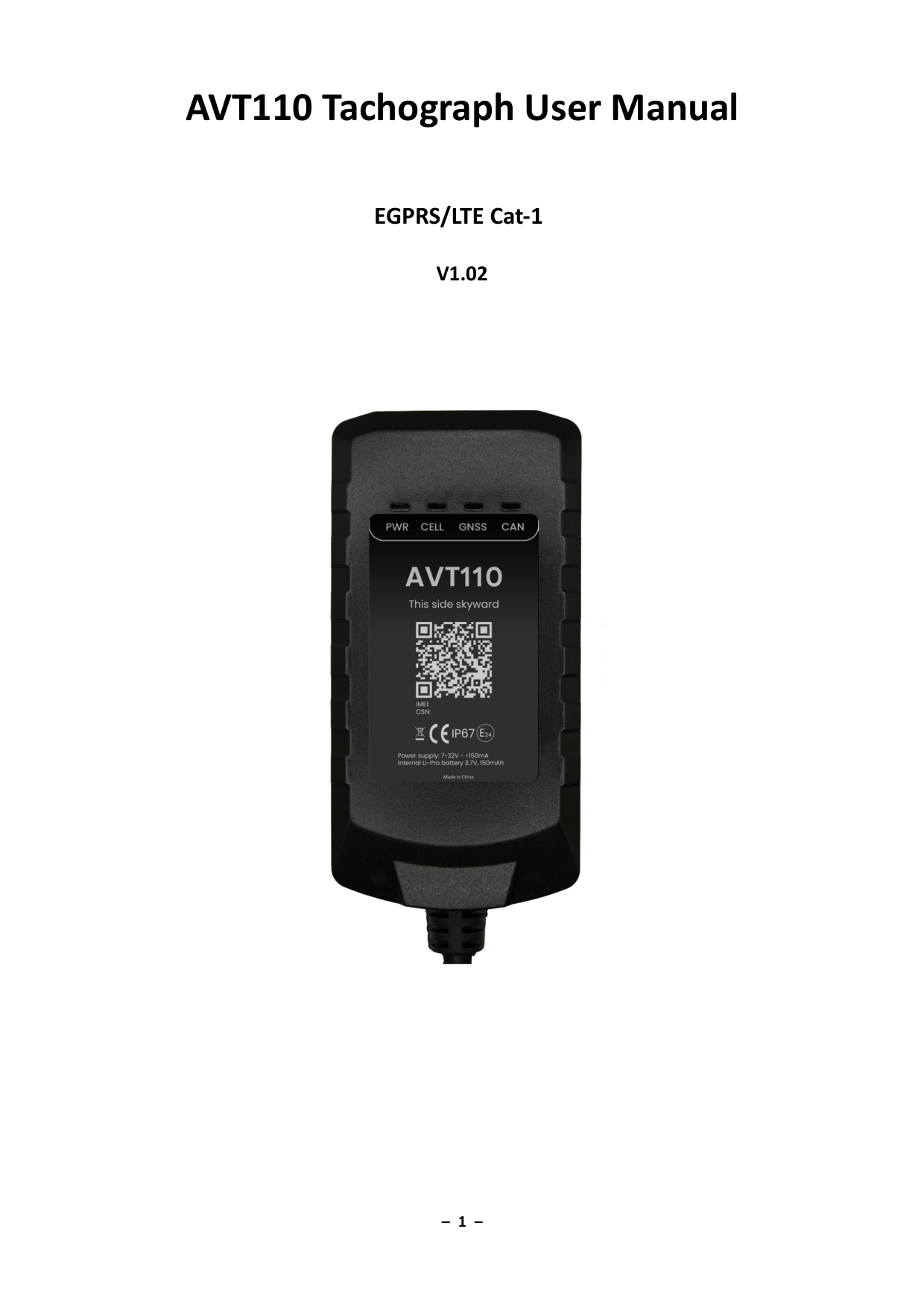
AVT110 Tachograph Manual
Version 1.02 — Jan 7, 2025
Installation and configuration guide for connecting the AVT110 to a digital tachograph — vehicle wiring, CAN/tacho settings, synchronization, and AT@TAC download parameters. For the Card Authorizer flow, REST API, and sequence diagram, see Tacho Information.
Connection FMS & tachograph connector for trucks
The FMS connector connects to CAN1 of the AVT110. FMS connector shape and pinout vary between truck makes and models — see the full PDF for an illustrative diagram. For CAN1 connection position, refer to the installation manual for the particular truck model. Installation diagram requests: support@iot-at.com
Connect the tachograph to CAN2, K-Line, and GND while the vehicle CAN-BUS connects to CAN1. If only the tachograph is connected, use CAN2, K-Line, GND, and run auto-synchronization.
CANbus & tacho configuration
- In CANbus & Tacho → CANbus settings, configure AT@CAN command Enable <mode> to 2 or 3.
- Very important: measure resistance on tachograph connector C pins 5/7 when CAN2 wires are connected and the tachograph is OFF. If it reads 120 Ω, configure the 120 Ω resistor in CANbus & Tacho → CANbus → AT@CAN. Final resistance on these pins should be 60 Ω.
- Configure AT@CAN to enable CAN2 L and CAN2 H parallel 120 Ω resistor (mask in <CAN 120 ohms Mask>). For some truck brands like Scania, only CAN1 may be used for the DDD download process.
- Enable <Tachograph Info Mask> — includes tachograph information, overspeed signal, vehicle motion signal, driving direction, driver 1/2 card numbers, driver 1/2 names, and real-time clock date/time.
CANbus synchronization
CANbus codes auto-synchronization lets the AVT110 detect the connected vehicle model. Switch ignition on and send AT@RTO=at,14,2,,,,,FFFF# after installation. Observe the CAN LED during synchronization. For synchronized ID details, refer to AT@RTO=at,14,0,,0001# (sub-command 14 in RTO — Real Time Operation).
| Connection | Synchronized groups |
|---|---|
| Truck — only CAN1 connected to FMS | 1, 30, 31 |
| Truck — CAN1 and CAN2 connected to tachograph | 75, 76, 77, 78, 83 |
| Truck — only CAN2 connected to tachograph | 79, 80 |
| Truck — J1708 connection | 70 |
DDD file request process
- Use the AT@TAC command to start DDD file download.
- DDD files can upload via +LDP messages to the server or FTP server, configured by <Report Mode> of AT@TAC.
- DDD files can be read from tachograph memory, Driver 1 card, and Driver 2 card — set via <Read File Type> of AT@TAC.
- <Start time> and <End time> are valid when <Read File Type> is set to 1 (request to read tachograph memory).
For Card Authorizer flow, REST API endpoints, and the interactive sequence diagram, see Tacho Information.
AVT110 Tachograph User Manual
v1.02 · 2025-01-07 · Release
Page 1 of 10
If the preview does not load, use Download or Open in new tab.