
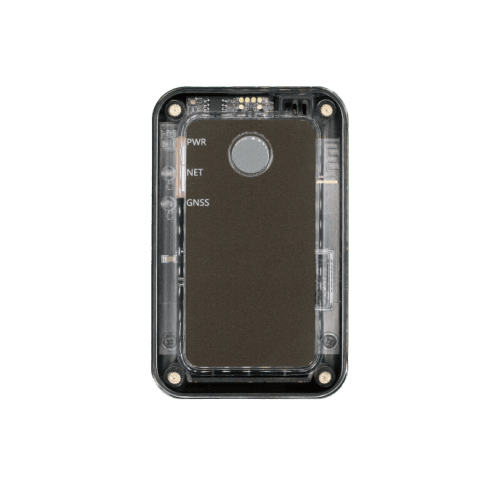
GPS Trackers
ATL100
Protocol
ATL100 Cold Chain Data Logger IoT Protocol
Revision 1.06 — Sep 21, 2025 — BLE scan settings (AT@BSS)
ATL100 Cold Chain Data Logger IoT Protocol R1.06 defines the data stream format, configuration commands, and message structures used between the ATL100 temperature data logger and backend server over CAT-M1 / NB-IoT / EGPRS. Use the sections below for a structured overview, or open the full PDF for complete command parameters and field definitions.
ATL100 — Protocol
v1.06 · 2025-09-21 · Release
Page 1 of 43
If the preview does not load, use Download or Open in new tab.
Revision history
| Revision | Date | Description |
|---|---|---|
| 1.00 | 2022-05-01 | Initial release |
| 1.01 | 2023-03-21 | SACK Enable in AT@SIS; AT@ETS external temperature; temperature zone in +RPT and GCS Data Mask; RTO sub-commands 8/9; Sample RTC Time Mask in AT@CCS; PT100 and DS18B20 1-Wire in AT@ETS |
| 1.02 | 2023-09-03 | Optimized AT command structure; GNSS enable logic for motion / stillness |
| 1.03 | 2024-04-10 | eMTC and EGPRS network scan mode in AT@NIS; Sensor Data Number in +RPT |
| 1.04 | 2025-03-16 | Search No Signal Cover in AT@NIS; Button Working Mode in AT@GCS; AT@DOG software watchdog |
| 1.05 | 2025-06-24 | No Moving Send Interval in AT@RRS; regular report mode 2 |
| 1.06 | 2025-09-21 | Added AT@BSS BLE scan settings command |
Data stream format
Communication includes upstream (device → server) and downstream (server → device) data streams over the cellular network. Upstream carries responses to downlink commands and unsolicited reports. Downstream carries configuration, query commands, and responses to uplink messages.
Frame types
| Direction | Encoding | Frame | Usage |
|---|---|---|---|
| Downstream | Printable ASCII | Configuration Command | Configure terminal parameters (AT@…=) |
| Downstream | Printable ASCII | Query Command | Query current parameters (AT@…?) |
| Downstream | Printable ASCII | +SACK | Server acknowledgement when the terminal sends a +RPT frame |
| Upstream | Printable ASCII | +QRY | Terminal response to a query command |
| Upstream | Printable ASCII | +ACK | Confirms a valid configuration command was received |
| Upstream | Hexadecimal | +RPT / -RPT | Real-time and buffered report messages |
Configuration commands
Configuration commands use the format AT@<KEY>=<password>,<parameters>,…,<serial># . Each command is protected by a password (default bcc100) and ends with a 4-digit hexadecimal serial number and "#".
Example — main server settings:
AT@SIS=bcc100,0,1,255.255.255.255,12345,,,0,0001#
Network commands
| Code | Command | Description |
|---|---|---|
| SIS | AT@SIS= | Main server IP, port, report mode (0 Stop / 1 TCP / 2 UDP), buffer mode, SACK enable |
| NIS | AT@NIS= | APN, credentials, network scan mode (0 auto, 1 EGPRS, 2 NB-IoT, 3 eMTC, 4 eMTC+NB2, 5 eMTC+EGPRS), Search No Signal Cover |
General commands
| Code | Command | Description |
|---|---|---|
| GMT | AT@GMT= | Greenwich Mean Time / time zone setting |
| GCS | AT@GCS= | Global configuration: +RPT Data Mask, LED mode, GNSS mode, GNSS Info Mask, power saving, power-on mode, button working mode |
| RRS | AT@RRS= | Regular report: mode (0 off / 1 mode1 / 2 mode2), sensor sample interval, send interval, no-moving send interval |
Cold chain commands
| Code | Command | Description |
|---|---|---|
| CCS | AT@CCS= | Cold chain settings: Cold Chain Info Mask, tilt, flight mode, motion/stillness, crash, light, built-in temperature/humidity alarms |
| ETS | AT@ETS= | External temperature sensors (PT100, DS18B20 1-Wire) alarm thresholds and duration |
Operations, OTA, and BLE
| Code | Command | Description |
|---|---|---|
| RTO | AT@RTO= | Real-time operation (reboot, power off, quick server debug, delete buffer messages, and more) |
| DOG | AT@DOG= | Software watchdog: mode and interval |
| UPF | AT@UPF= | Firmware upgrade over the air |
| BMS | AT@BMS= | Device management system: BMS server, report interval, +BMR Data Mask |
| BSS | AT@BSS= | BLE scan settings (added in v1.06) |
Query commands
Query commands retrieve the current working parameters of the terminal. They use printable ASCII with comma-separated fields:
AT@<KEY>?<password>,,<serial>#
- AT@SIS?bcc100,,# — query main server settings
- AT@NIS?bcc100,,# — query network (APN) settings
- AT@GMT?bcc100,,# — query time settings
- AT@GCS?bcc100,,# — query global configuration
- AT@RRS?bcc100,,# — query regular report settings
- AT@CCS?bcc100,,# — query cold chain settings
Message format
Report messages share a common frame structure with header, data, and tail zones:
| Zone | Fields | Encoding |
|---|---|---|
| Header | Head (5 B) + Length (2 B) + IMEI (8 B) + Device ID (1 B) | ASCII / HEX / HEX / HEX |
| Data | Variable payload + G-time (7 B) | HEX or ASCII |
| Tail | Serial number (2 B) + Tail "#" (1 B) | HEX / ASCII |
- +RPT / -RPT and +BMR / -BMR — data zone encoded in hexadecimal (big-endian for multi-byte values)
- +SACK — fully ASCII encoded
- +ACK, +QRY, +ALL, +QNI, +VER — data zone in ASCII with comma separators
Report messages (+RPT / -RPT)
+RPT frames are real-time reports generated and sent within 3 minutes. -RPT frames are historical reports stored in the device buffer and sent when connectivity is restored.
All event-driven and regular reports share the same +RPT/-RPT hex-encoded format. The Data Mask in AT@GCS controls which information zones are included in each report.
Key +RPT Data Mask bits (AT@GCS)
| Bit | Field | Content |
|---|---|---|
| 0 | Multi-packet | Frame count and frame ID |
| 1 | Network type | Cellular network type |
| 2 | Battery | Voltage (mV) and level (%) |
| 3 | GNSS information | Fix type, HDOP, speed, azimuth, altitude, lat/lon, UTC time |
| 4 | Cell information | MCC, MNC, LAC, Cell ID, CSQ |
| 5 | Neighboring cell | Adjacent cell information |
| 6 | Cold chain information | Temperature, humidity, light, motion, 1-Wire sensors |
| 7 | Upgrade information | Firmware upgrade status |
| 19 | BLE information | BLE scan results |
Event types
| Type | Event |
|---|---|
| 0 | Terminal power |
| 1 | Regular report |
| 2 | Moving |
| 3 | Battery alarm |
| 4 | Free fall alarm |
| 5 | Tilt alarm |
| 6 | Flight mode |
| 7 | Crash alarm |
| 8 | Light alarm |
| 9 | Built-in temperature alarm |
| 10 | Humidity alarm |
| 11 | Upgrade firmware |
| 12 | External temperature alarm |
| 30 | BLE common info |
Buffer messages (+BMR / -BMR)
+BMR frames are real-time BMS reports generated and sent within 3 minutes. -BMR frames are buffered BMS reports sent when connectivity is restored. Configure BMS reporting via AT@BMS.
| Parameter | Description |
|---|---|
| Report Mode | 0 = Stop, 1 = TCP |
| Buffer Mode | 0 = disabled, 1 = enabled |
| BMS Server IP / Port | Device management server address |
| Connection Life | 0 or 5–300 seconds |
| Report Interval | 1–2880 minutes |
| BMR Data Mask | Component mask for +BMR/-BMR message content (set via AT@BMS) |
Acknowledgement
| Frame | Direction | Description |
|---|---|---|
| +ACK | Device → server | Confirms a valid configuration command was received |
| +SACK | Server → device | Server acknowledgement when SACK Enable is set in AT@SIS |
Command query responses
| Frame | Description |
|---|---|
| +QRY | Response to a single query command |
| +ALL | Bulk response with all configured parameters |
| +QNI | Network information query response (APN, IMSI, ICCID, CSQ, cell ID) |
| +VER | Firmware and hardware version information |
Terms and abbreviations
| Term | Meaning |
|---|---|
| ACK | Acknowledgement |
| APN | Access Point Name |
| BLE | Bluetooth Low Energy |
| CCS | Cold Chain Setting |
| EGPRS | Enhanced General Packet Radio Service |
| G-Time | Generated Time |
| GNSS | Global Navigation Satellite System |
| IMEI | International Mobile Equipment Identity |
| IoT | Internet of Things |
| NB-IoT | Narrowband IoT |
| RPT | Report message |
| SACK | Server acknowledgement |
| TCP / UDP | Transmission Control / User Datagram Protocol |
| UTC | Coordinated Universal Time |