
GPS Trackers
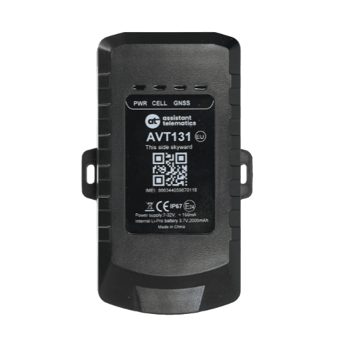
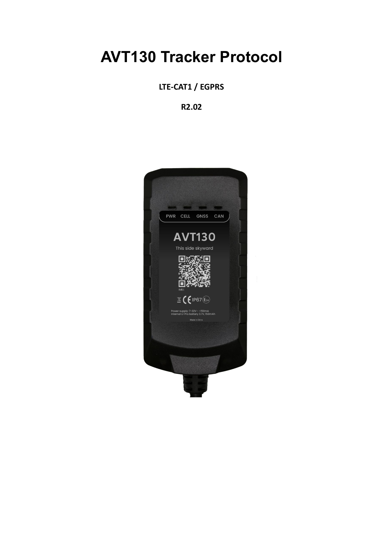
AVT130 / AVT131
RS232 Protocol
AVT130/AVT131 RS232 Tracker Protocol
Revision 2.02 — Jun 23, 2026 — BLE BBS/TRB transparent transmission, extended +DFI, tachograph DDD via +LDP
AVT130/AVT131 RS232 Tracker Protocol R2.02 defines the data stream format, configuration commands, and message structures used between the AVT130/AVT131 LTE Cat-1/EGPRS trackers and backend server. These trailer trackers support UART/RS232 transparent transmission, BLE accessories, and long standby battery operation. Use the sections below for a structured overview, or open the full PDF for complete command parameters and field definitions.
AVT130 / AVT131 — RS232 Protocol
v2.02 · 2026-06-23 · Release
Page 1 of 94
If the preview does not load, use Download or Open in new tab.
Revision history
| Revision | Date | Description |
|---|---|---|
| 1.01 | 2024-01-30 | Initial release |
| 1.02 | 2024-12-25 | AT@PCL/ECL; UART transparent mode in AT@URT; AT@TRS; delta AIS in AT@DAM; output alarm and new +RPT event types |
| 1.03 | 2025-03-09 | Driver ID whitelist up to 1024 entries in AT@DRV |
| 1.04 | 2025-03-19 | AT@BSS BLE scan; AT@ETS/EHS external sensors; external humidity event; PDP Enable in AT@SIS |
| 1.05 | 2025-06-10 | AT@JAM jamming detection; network module OTA in AT@UPF; jamming alarm event (32) |
| 1.06 | 2025-07-08 | Module version in +BMR; Apache FMA1000 thermograph type in AT@URT |
| 1.07 | 2025-08-07 | Second server SSI; TLS (TCR/TCL); MQTT (MQT); Resend Time No SACK in AT@SIS |
| 1.08 | 2025-09-24 | AT@PEO polygon fence; GNSS timeout; BLE relay and iBeacon settings |
| 2.01 | 2026-01-12 | AT@GGF geo-fence GNSS filter; GNSS spoofing alarm; extended BLE features |
| 2.02 | 2026-06-23 | Latest release — PEO events, +LDP large data packets, +DFI device file info |
Data stream format
Communication includes upstream (device → server) and downstream (server → device) data streams over the cellular network. Upstream carries responses to downlink commands, heartbeat packets, and unsolicited reports. Downstream carries configuration, query commands, and responses to uplink messages.
Frame types
| Direction | Encoding | Frame | Usage |
|---|---|---|---|
| Downstream | Printable ASCII | Configuration Command | Configure terminal parameters (AT@…=) |
| Downstream | Printable ASCII | Query Command | Query current parameters (AT@…?) |
| Downstream | Printable ASCII | +SACK | Server acknowledgement for +RPT messages |
| Downstream | Printable ASCII | +SHBD | Server response to +HBD heartbeat |
| Upstream | Printable ASCII | +QRY | Terminal response to a query command |
| Upstream | Printable ASCII | +HBD | Periodic heartbeat to maintain TCP/UDP connectivity |
| Upstream | Printable ASCII | +ACK / +NACK | Acknowledgement or rejection of configuration commands |
| Upstream | Hexadecimal | +RPT / -RPT | Real-time and buffered report messages |
Configuration commands
Configuration commands use the format AT@<KEY>=<password>,<parameters>,…,<serial># . Each command is protected by a password (default at) and ends with a 4-digit hexadecimal serial number and "#".
Example — main server settings:
AT@SIS=at,0,1,255.255.255.255,12345,,,0,0001#
Network commands
| Code | Command | Description |
|---|---|---|
| SIS | AT@SIS= | Main server IP, port, report mode (0 Stop / 1 TCP / 2 UDP / 3 MQTT), buffer, SACK enable, heartbeat, PDP/TLS, message filter, Resend Time No SACK |
| SSI | AT@SSI= | Second server settings (same parameters as SIS) |
| NIS | AT@NIS= | APN, credentials, network scan mode, Search No Signal Cover |
| MQT | AT@MQT= | MQTT client ID, topics, QoS, keep-alive (main or second server) |
| TCR | AT@TCR= | TLS certificate remote download (HTTP) |
| TCL | AT@TCL= | TLS certificate local download |
| FTP | AT@FTP= | FTP server settings for tachograph DDD and diagnostic file upload |
General commands
| Code | Command | Description |
|---|---|---|
| GMT | AT@GMT= | Greenwich Mean Time / time zone setting |
| GCS | AT@GCS= | Global configuration: Data Mask (incl. BLE, RS485/RS232 accessory masks), Event Data Mask (incl. PEO status bits 21/24, CAN sync bit 25), LED, GNSS/AGPS, odometer, hour meter, GNSS timeout |
| RRS | AT@RRS= | Regular GNSS report: mode, IGN/IGF intervals, corner angle, long standby wake-up |
| RTO | AT@RTO= | Real-time operation: reboot, power off, factory reset, realtime positioning, CAN module ops, +DFI, +CVS, +CMI, report mode |
| PCL | AT@PCL= | Preset command list (up to 32 commands) |
| ECL | AT@ECL= | Event-driven command list with ECL Trigger Report |
| GGF | AT@GGF= | Geo-fence GNSS filter and spoofing detection settings |
Alarm commands
| Code | Command | Description |
|---|---|---|
| MOV | AT@MOV= | Movement alarm with Motion Event Report |
| TOW | AT@TOW= | Towing (TOW) alarm detection |
| SPD | AT@SPD= | Speed alarm threshold and duration |
| GEO | AT@GEO= | Circular geo-fence settings (up to 32 zones) |
| PEO | AT@PEO= | Polygon fence settings (up to 50 zones) |
| HBS | AT@HBS= | Harsh behavior (driving style) with trigger interval |
| CRA | AT@CRA= | Crash detection with crash debounce |
| JAM | AT@JAM= | Jamming alarm (LTE and GSM signal thresholds) |
| TAS | AT@TAS= | Tilt alarm detection |
I/O commands
| Code | Command | Description |
|---|---|---|
| IGN | AT@IGN= | Ignition and virtual ignition; Ignition On limit outputs mask, GNSS speed limit, debounce |
| DAM | AT@DAM= | Digital and analog input multiplexing (incl. delta AIS) |
| OUT | AT@OUT= | Digital output settings |
| AOS | AT@AOS= | Alarm output mapping and trigger masks (incl. jamming trigger) |
1-Wire and UART commands
| Code | Command | Description |
|---|---|---|
| WAS | AT@WAS= | 1-Wire application settings |
| WOS | AT@WOS= | 1-Wire alarm output settings |
| ETS | AT@ETS= | External temperature sensors (1-Wire and BLE) |
| EHS | AT@EHS= | External humidity sensors (BLE) |
| DRV | AT@DRV= | Driver ID settings (up to 1024 driver IDs) |
| URT | AT@URT= | Serial port settings: thermograph types, baud rate, mode (incl. UART transparent transfer) |
| TRS | AT@TRS= | Transparent transmission from server to RS232/UART serial port |
BLE commands
| Code | Command | Description |
|---|---|---|
| BSS | AT@BSS= | BLE scan settings, iBeacon UUID filter, BLE Event Data Mask |
| BBS | AT@BBS= | BLE broadcast settings |
| BCS | AT@BCS= | BLE connection settings (ABK100, ABR100 relay encryption) |
| BRY | AT@BRY= | BLE relay output control |
| BOS | AT@BOS= | BLE alarm output wave shape |
| TRB | AT@TRB= | BLE transparent transmission to server via +LDP message |
OTA and debug
| Category | Code | Description |
|---|---|---|
| OTA | UPF | Firmware upgrade over the air (main MCU, network module, boot firmware) |
| OTA | UPC | Configuration upgrade over the air |
| OTA | BMS | Device management system: BMS server, report mode (Stop/TCP/UDP/MQTT), +BMR Data Mask |
| DEBUG | DBG | OTA debug log server and log mask |
Query commands
Query commands retrieve the current working parameters of the terminal. They use printable ASCII with comma-separated fields:
AT@<KEY>?<password>,,<serial>#
- AT@SIS?at,,# — query main server settings
- AT@SSI?at,,# — query second server settings
- AT@NIS?at,,# — query network (APN) settings
- AT@TAC?at,,# — query tachograph DDD file request settings
- AT@URT?at,,# — query serial port / RS232 settings
- AT@GCS?at,,# — query global configuration
- AT@PEO?at,,# — query polygon fence settings
Message format
Report, buffer, large-data, and heartbeat messages share a common frame structure with header, data, and tail zones:
| Zone | Fields | Encoding |
|---|---|---|
| Header | Head (5 B) + Length (2 B) + IMEI (8 B) + Device ID (1 B) | ASCII / HEX / HEX / HEX |
| Data | Variable payload + G-time (7 B) | HEX or ASCII |
| Tail | Serial number (2 B) + Tail "#" (1 B) | HEX / ASCII |
- +RPT / -RPT, +LDP / -LDP, +BMR / -BMR, +HBD — data zone encoded in hexadecimal (big-endian for multi-byte values)
- +LDP / -LDP — large data packets for tachograph DDD files, BLE transparent data, and other oversized payloads
- +SACK / +SHBD — fully ASCII encoded
- +ACK, +QRY, +ALL, +QNI, +VER, +GSV, +LSV, +BSV, +GAV, +CVS, +CMI, +SCF, +TCF, +DFI — data zone in ASCII with comma separators
Report messages (+RPT / -RPT)
+RPT frames are real-time reports generated and sent within 3 minutes. -RPT frames are historical reports stored in the device buffer and sent when connectivity is restored.
All GNSS-related messages and events share the same +RPT/-RPT hex-encoded format. The Data Mask and Event Data Mask in AT@GCS control which information zones are included, including BLE, RS485/RS232 accessory, and event data.
Key +RPT Data Mask bits (AT@GCS)
| Bit | Field | Content |
|---|---|---|
| 0 | Multi-packet | Auto-enabled when message exceeds 256 bytes |
| 1 | Network type | Cellular network type |
| 2 | Battery | Voltage (mV) and level (%) |
| 3 | GNSS information | Fix type, HDOP, speed, azimuth, altitude, lat/lon, UTC time, satellite counts |
| 4 | Cell information | MCC, MNC, LAC, Cell ID, CSQ |
| 7 | Upgrade information | Firmware upgrade status |
| 8 | Event data | Main power, ignition, motion, mileage, GEO/PEO status, hour meter, crash, tilt, TLS, digital I/O, CAN sync |
| 17 | Special car information | Vehicle-specific CAN data fields |
| 19 | BLE information | BLE scan results and sensor data |
| 20 | BLE iBeacon | iBeacon scan results |
Event types
| Type | Event |
|---|---|
| 0 | Terminal power |
| 1 | Regular report |
| 2 | Moving |
| 3 | Battery alarm |
| 7 | Crash alarm |
| 11 | Upgrade firmware |
| 12 | External temperature alarm |
| 13 | Ignition |
| 14 | Main power alarm |
| 15 | Tow alarm |
| 16 | Over speed alarm |
| 19 | Harsh behavior alarm |
| 21 | Geo-fence alarm |
| 24 | CANBUS info event |
| 30 | BLE common info |
| 31 | External humidity alarm |
| 32 | Jamming alarm |
| 35 | TLS certificate download |
| 38 | Upgrade configuration |
| 39 | GNSS spoofing alarm |
| 40 | PEO fence alarm |
| 41 | PEO fence over-speed alarm |
| 44 | BLE slave connect event |
Buffer messages (+BMR / -BMR)
+BMR frames are real-time BMS reports. -BMR frames are buffered BMS reports sent when connectivity is restored. Configure via AT@BMS.
| Parameter | Description |
|---|---|
| Report Mode | 0 = Stop, 1 = TCP, 2 = UDP, 3 = MQTT |
| Buffer Mode | 0 = disabled, 1 = low priority, 2 = high priority |
| BMS Server IP / Port | Device management server address |
| Connection Life | 0 or 5–300 seconds TCP keep-alive |
| Report Interval | 1–2880 minutes |
| BMR Data Mask | Battery level, config version, IGN state, GNSS info, SIM info, module version, boot firmware |
Heartbeat and acknowledgement
| Frame | Direction | Description |
|---|---|---|
| +HBD | Device → server | Periodic heartbeat when report mode is TCP or UDP (interval set in AT@SIS) |
| +SHBD | Server → device | Server response to +HBD |
| +ACK | Device → server | Confirms a valid configuration command was received |
| +NACK | Device → server | Rejects an illegal configuration command |
| +SACK | Server → device | Server acknowledgement when SACK Enable is set |
Command query responses
| Frame | Description |
|---|---|
| +QRY | Response to a single query command |
| +ALL | Bulk response with all configured parameters |
| +QNI | Network information (APN, IMSI, ICCID, CSQ, cell ID) |
| +VER | Firmware and hardware version information (incl. boot firmware) |
| +GSV | GPS satellite visibility |
| +LSV | GLONASS satellite values |
| +BSV | BEIDOU satellite values |
| +GAV | GALILEO satellite values |
| +CVS | CAN module version and serial number (via AT@RTO sub-command 13) |
| +CMI | CAN module car model ID (via AT@RTO sub-command 14) |
| +SCF | Server configuration fields |
| +TCF | Terminal configuration fields |
| +DFI | Device file information (via AT@RTO sub-command 16): main power, battery, I/O state, BLE modes, analog input, total distance |
Terms and abbreviations
| Term | Meaning |
|---|---|
| ACK | Acknowledgement |
| APN | Access Point Name |
| BLE | Bluetooth Low Energy |
| GNSS | Global Navigation Satellite System |
| IMEI | International Mobile Equipment Identity |
| IoT | Internet of Things |
| LDP | Large data packet message |
| MQTT | Message Queuing Telemetry Transport |
| PEO | Polygon fence (geo zone) |
| RS232 | Recommended Standard 232 serial interface |
| RPT | Report message |
| SACK | Server acknowledgement |
| TCP / UDP | Transmission Control / User Datagram Protocol |
| TLS | Transport Layer Security |
| UART | Universal Asynchronous Receiver-Transmitter |
| UTC | Coordinated Universal Time |